


Share by email
Your message was succesfully sent!
Add The Following Snippet To Your Html


DETAILED DESCRIPTION
INTRODUCTION
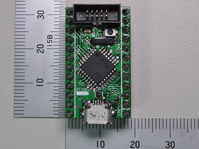
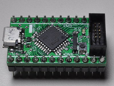
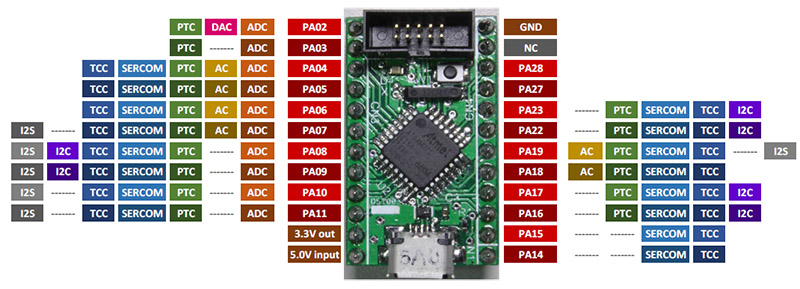
The SAMD21-DIP24 is a small form factor MCU board for the Atmel SAM D21 series. Its design goal was to achieve a small size as possible in a form of a handy DIP package type module with the powerful 32bit MCU and an USB device capability. The PCB is same size as the standard 600mil wide DIP 24pin package. Therefore, this board will be suitable for a project, which requires a small form factor PCB, or a quick prototyping using a breadboard.
HARDWARE
4 variants of ARM Cortex-M0+ based Atmel SAM D21 series microcontrollers with a TQFP 32pin package can be used for this board.
- ATSAMD21E18 256KB Flash, 32KB SRAM
- ATSAMD21E17 128KB Flash, 16KB SRAM
- ATSAMD21E16 64KB Flash, 8KB SRAM
- ATSAMD21E15 32KB Flash, 4KB SRAM
These variants are all pin compatible and the only difference is its Flash and SRAM size. You can choose the device according to requirement for the Flash and SRAM size. The board has a Micro USB Type B connector (CN1) and can provide power to the board through this USB connector. Power can be also provided by the DIP pin 12 (CN3). TLV1117LV (U3) is used for generating a 3.3V logic power from 5V. The maximum output current of TLV1117V is 1A. Please note that the absolute maximum input voltage of TLV1117V is 6.0V. The board has a 32.768kHz crystal (X1) for the MCU and outputs of the crystal are connected to the XIN32 pin and XOUT32 pin of the MCU. The SAMD21 can generate high frequency clocks (48/96MHz) that are needed for the MCU core and the USB modules from this crystal. The board has a Cortex 10-pin 0.05" Serial Wire Debug (SWD) interface connector (CN2) for flashing and debugging a MCU software. The board equips one tact switch (SW1) to reset the MCU and one LED (D4) as a power indicator.
SOFTWARE
I am using Atmel Studio Version 7 and j-link to develop and download my software into the SAMD21-DIP24 board.
Atmel Studio 7
http://www.atmel.com/Microsite/atmel-studio/
j-link
https://www.segger.com/jlink-debug-probes.html
I made the following simple LED blinking program for testing the board.
LEDs are connected to all available ports on the boards.
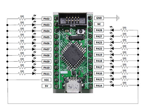
You can download the test firmware and source codes from the attachment at the bootom of this page.
HOW TO MAKE THE PCB
I used seeed studio’s Fusion PCB service to manufacture the PCB.
Fusion PCB service:
http://www.seeedstudio.com/service
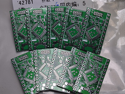
Here is the Gerber Files zip that I used for manufacturing the above PCB at the Fusion PCB service.
Design files
Authors
- /
- Active Participants


Components & Releases
Fabricate
Delete release
Are you sure you want to delete this Release?
This action cannot be undone.
Unable to download from CircuitMaker
You cannot download files inside CircuitMaker.
Please, open this page in browser and download file from there.
To copy hyperlink, press Ctrl+C with selected text below:


Comments ()