


Share by email
Your message was succesfully sent!
Add The Following Snippet To Your Html


DETAILED DESCRIPTION
Why?
Fun! This project was intended as a challenge to fit as much useful circuitry as I could onto a tiny, strange form-factor board. Eventually (after some external mechanical design), this can be able to be made into a wearable pin.
Core Features:
Atmega32u4 main processor, with schematic and pin numbering borrowed from the Arduino project (with which this project is not affiliated). Reprogrammable over USB.
RGB LED Eye: Everything's got to have some RGB.
6-DOF IMU (LSM6DS3): 3-axis Gyro and Accel, communicates over I2C. Common library support available.
Bluetooth Low-Energy: BlueNRG-MS chip, with a BLE antenna on the rear leg.
Lithium-Ion Polymer Battery powered: Main logic is powered by a boost from battery voltage to 5V. USB feeds an on-board battery charger to charge the battery. The main boost has a true-off mode so when it's disabled, it draws extremely little current, for long battery life. The intention when this is actually made into a wearable pin is to use the closing of the pin itself into the enable circuitry.
Absolutely Tiny: I mean, look at the photos! I've designed a variety of fun hobbyist electronics projects before that used the Arduino platform. As mentioned above, the way I made this project fun for myself was to try to cram as much circuitry as I could into a tiny, strange form-factor. What resulted was using every facet of extended manufacturing capability provided by Macrofab (3/3 traces, 4 mil vias) plus one feature that wasn't listed online (epoxy filled vias, since I had to do via in pad for the BGAs).
Project State:
I have 3 built boards back. Initially, there were shorts on all 3 boards between two pins on the battery charging IC that caused it to not charge at all, ever. The Atmega32u4 was also installed 180 degrees off. I can't blame my manufacturer for this too much because I used the standard library footprint and didn't notice it didn't have a silkscreen pin 1 marking. Oops. I have boards back from Manufacturer RMA rework, and now things seem to work well, less that I haven't had time to do the careful, current-limited testing I want to do on the battery charging circuitry. Apart from that, the power supplies (5V boost, 3.3V high-PSRR LDO) look good, the RGB LED Eye works well, as does the 6-DOF IMU. For the 6-DOF, I after building the board I noticed that I didn't strap the address pin correctly. I seem to be being saved by an internal pull-up resistor that reliably straps the pin high on the board I've tested, but I don't yet know if that's just a battle of the bias currents that could be different on each board. I've brought up the BlueNRG-MS BLE chip enough to know that I can talk SPI to it and it responds appropriately, but there will be a bunch more driver code I need to write before I know for sure that it's fully working.
Here is the ripple on the boost 5V rail with 3.7Vin. The Atmega is running and one of the RGB Eye LEDs is on. This was captured on a 200MHz scope, using 200MHz 10x probes in AC coupled mode. I used the ground spring and probed a GND and 5V testpoint. This is an acceptable measuring strategy for my purposes. A slight upgrade would have been to measure closer to the actual output of the regulator itself, but I didn't want to bother with soldering probes in. The gold standard for my ecosystem would be an N7020A probe, but it's $$$$, and my particular scope can't drive it anyway.
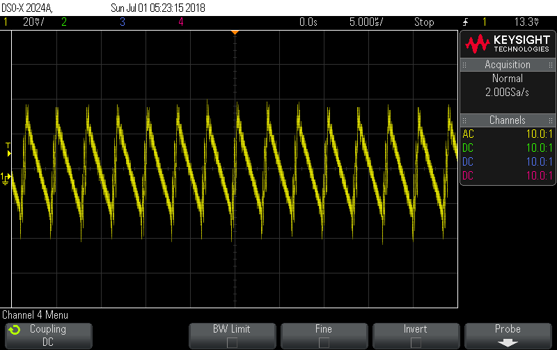
80mV pk-pk ripple under load is more than I perhaps would have liked, but it's acceptable for the 5V supply, especially on a board where the most sensitive analog measurement is the battery supply voltage.
In contrast, here's the 3.3V rail, measured on the same setup:
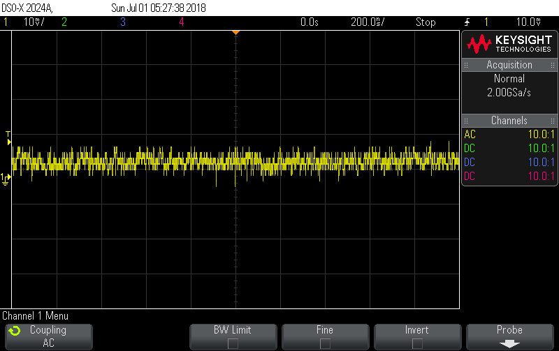
This is pretty much in the noise of my oscilloscope. This is the advantage of selecting a regulator with an awesome Power Supply Ripple Rejection (PSRR). When designing this board, I knew that the 3.3V regulator would be powering the BlueNRG Bluetooth IC, so I wanted it to be as clean as possible.
Design files
Authors
- /
- Active Participants


Components & Releases
Fabricate
Delete release
Are you sure you want to delete this Release?
This action cannot be undone.
Unable to download from CircuitMaker
You cannot download files inside CircuitMaker.
Please, open this page in browser and download file from there.
To copy hyperlink, press Ctrl+C with selected text below:


Comments ()