


DETAILED DESCRIPTION
Product Requirements
The BLDC Controller is designed to be a part of a multicopter, thus the following Product Requirements are needed:
- Starting and controlling the output power (PWM only, not RPM) of a DC brushless motor without hall sensors
- Direction of rotation configurable
- Communication over I2C
- Power supply range for a 3-cell LiPo Battery (8V...13V)
- Current and supply voltage measurement
- Temperature measurement
- Optical status signalling
Theory of Operation
BLDC motors are 3-phase motors that need a rotating forcefield. This is created by changing currents for the 3 coils of the motor with a 120° phaseshift. There are two commonly used types of waveforms: sinusoidal and trapezoidal wave. Sinusoidal commutation is used with motors that provide hall sensors and it is way more complex to implement than trapezoidal commutation. For this product the trapezoidal waveform is used and further described.
Trapezoidal Commutation
The image (from Atmel AVR444) shows the 6 states during the commutation:
| State | Phase U | Phase V | Phase W |
|---|---|---|---|
| 1 | Low | High | floating |
| 2 | Low | floating | High |
| 3 | floating | Low | High |
| 4 | High | Low | floating |
| 5 | High | floating | Low |
| 6 | floating | High | Low |
The next commutation step is triggered by the floating phase. The floating phase is compared to sum of the three phases. When the floating phase exceeds the sum voltage (zero crossing) the controller doesn't directly switch to the next phase, it waits the same amount of time it already spent in that state. The circuit for comparing the phases is called Back electromotive force (Back EMF) network. In reality the feedback lines have to be low pass filtered and the sum voltage is generated by a resistor network.
The speed can be controlled by the voltage of the high level phase which can be varied through pulse width modulation (PWM). To change the spinning direction, you simply run the states from 6 to 1 instead from 1 to 6.
More information can be found in AVR444 in the attachments.
Implementation
Hardware
The circuit consists of the following parts:
- Powerstage: half-bridge driver + power MOSFETs
- Back EMF network
- Microcontroller
- Communication ports
- Optical signalling
- Sensors for current, temperature, voltage
Powerstage
The LM5106 from Texas Instruments is used to drive the N-channel MOSFETs. It would also be possible to use a N-channel MOSFET for the lower part and P-channel for the upper part of the half bridge without a half-bridge driver, but the advantage of the driver is that it uses two N-channel MOSFETs. These have better performance and are cheaper than P-channel MOSFETs.
The image (from the LM5106 datasheet) shows the IC circuitry, information about the function is placed below:
To be conductive a N-channel MOSFET transistor needs a positive voltage between the gate and the source (the exact value can be examined in the transistor datasheet). The problem is when the upper transistor is turned on, the source voltage reaches the same value as the supply voltage. But when the source voltage is the same as the supply voltage how can the gate-source voltage be positive? The answer is bootstrap: When the lower transistor is on the output gets 0V. Now the capacitor is being charged over the diode by VDD. The lower transistor is then turned off and the upper one is turned on, the output reaches VDD, but the voltage at the capacitor is still higher than VDD and thus can provide a positive gain-source voltage.
The LM5106 has an additional feature which is called dead time delay (leading edge delay). During the process of switching one transistor off and the other on, is a short time in the transient when both transistors are partly on. This causes a short circuit and an unnecessary current flow. The dead time delay waits after one transistor is off until it turns on the other one. The delay can be controlled by the resistor at the RDT input.
Microcontroller
An Atmel XMEGA 16D4 is used to control the motor. It provides the needed comparator for the back EMF as well as ADC ports and enough PWM outputs. The XMEGA series is used because it sources faster clockspeeds, better timers and peripheral interfaces than the MEGA series. The controller can be programmed over PDI (Program and Debug Interface) e.g. with an Atmel MKII.
Other Parts...
...are described in the schematics in the comment section.
Firmware
The firmware was written in Atmel Studio in C. The source code can be found in the attachments.
A simple architecture is used to separate the layers:
- Driver: drive the MCU peripherals such as timer and PWM
- Controller: run the communication and commutation task (both interrupt driven)
- Application: simple motor supervision and status visualisation
The firmware uses the same 6 states described in the Trapezoidal Commutation section.
Currently (V1.0) the firmware supports the following functions:
- Starting the motor using forced commutation
- The PWM supports 9-bit resolution (512 values)
- Over I2C the speed can be set
- Non-volatile storage of motor direction
- Status signalling
Result
Hardware
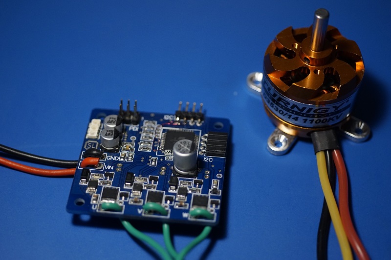
The board uses a size of 50mm x 50mm x 1.6mm with two copper layers and most importantly: it works! The only issue I had, was the overvoltage on the half-bridge drivers. But that can be solved with TVS diodes (added in revision 1.2).
In top left corner are three leds which show whether the board is running (top, green), the communication traffic (middle, green) and errors (bottom, red) e.g. when the motor is beeing blocked.
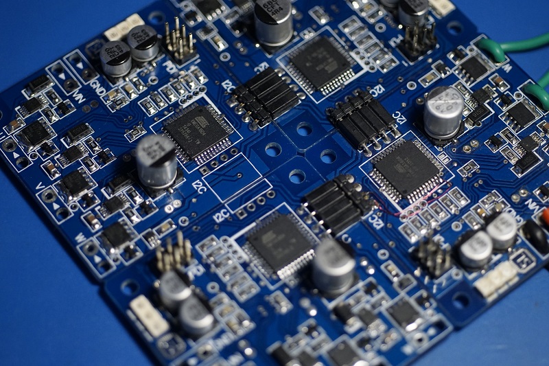
The I2C connectors are layed out in a way they can be interconnected with four boards.
Measurements
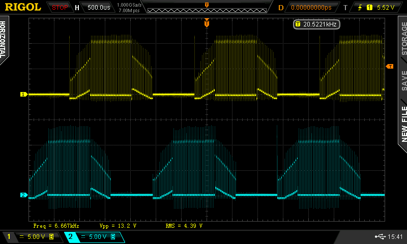
Motor terminal volatage vs time
The chart shows the the phases U and V over time (PWM is set to 50%). The trapezoidal output waveform and the phaseshift is clearly visible.
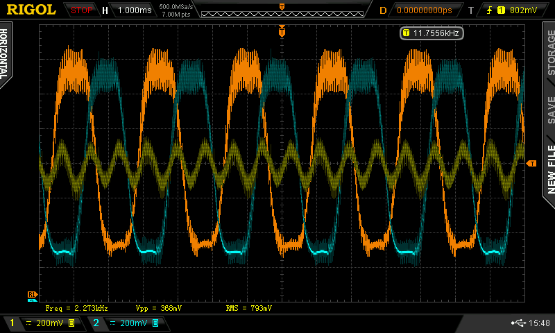
Back EMF voltage vs time
Yellow: Sum voltage, oragne: pahse U, blue: phase V; all low-pass filtered and divided
A zero-crossing happens when one of the phases (U, V or W) cross the the sum voltage. The motor controller is only sensitive for one phase. It can be seen that the sum voltage is not as flat and the phases are noisier as in the theoretical description of the commutation principle.
Future Work
- The project was originally designed in Altium Designer 10 and then incorrectly imported to CircuitMaker: all footprints on the bottom Layer do not show up.
The parts have to be linked to the octopart library. During speed changes of the motor produces overvoltage on the half-bridge driver, an protection diode is needed.- FW: Implement temperature, current and voltage reading
ECO for Revision 1.0
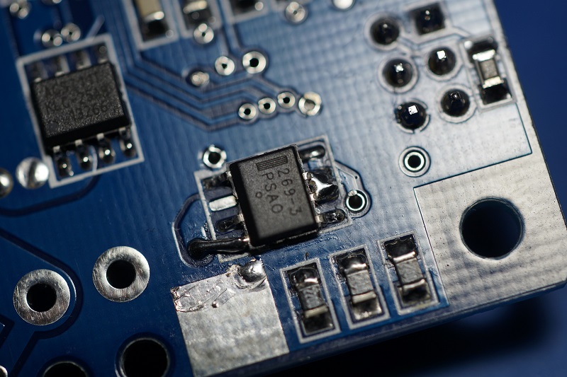
I'm using the PCBs from version 1.0 (the gerber data for Seeedstudio can be found in the attachments) unfortunately the LDO AP1120SBL is obsolete. It can be replaced with MC33269D-3.3G with some modification.
Pin 2 and 8 of the MC33269D-3.3G have to be removed. Pin 6 and 7 must be soldere together and finally a wire has to be soldered from pin 4 to the nearest via.
Authors
- /
- Active Participants

Components & Releases

Fabricate
Delete release
Are you sure you want to delete this Release?
This action cannot be undone.
Unable to download from CircuitMaker
You cannot download files inside CircuitMaker.
Please, open this page in browser and download file from there.
To copy hyperlink, press Ctrl+C with selected text below:




Comments ()