


Share by email
Your message was succesfully sent!
Add The Following Snippet To Your Html


DETAILED DESCRIPTION
This project is an import from Altium Designer 17, thus parts are not linked to the CircuitMaker Library. I tried to save costs by using parts I had laying around. There are parts that are obsolete or recommended to upgrade. However, a BOM with the parts I used is in the attachments.
Idea
Soldering SMD components by hand is quite a tedious job, especially QFN packages or if you have more than one board to assemble. Furthermore, are solder mask stencils getting cheaper.
There are some IR reflow oven available from chinese sellers, but these have bad reviews. Another solution is the use of a toaster oven. They are normally inexpensive and able to reach a max temperature of 230°C which is enough for lead solder. To successfully reflow an assembly a reflow profile has to be followed.
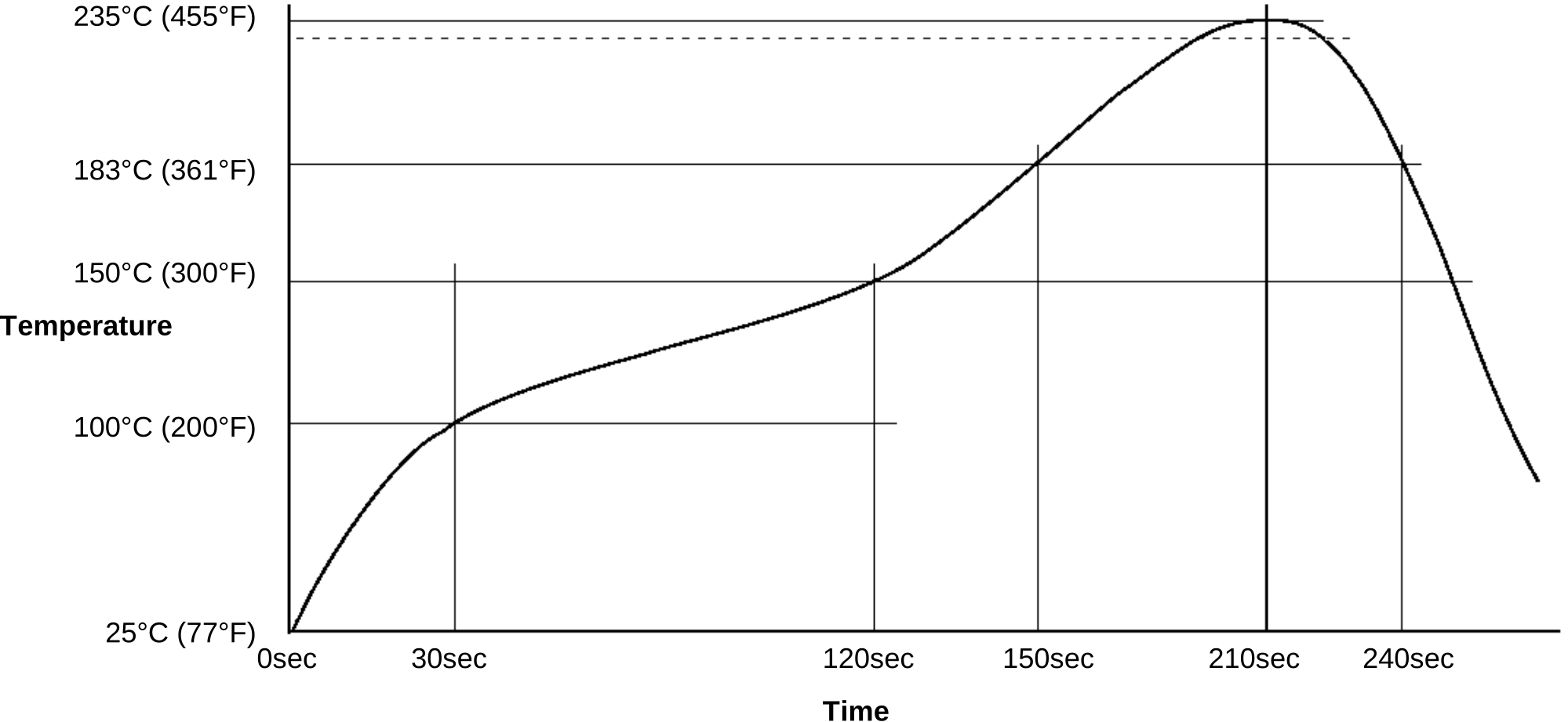
Source: ChipQuick TS391AX50 Lead Solder Paste Datasheet
The image shows the temperature profile for the lead solder I bought. A temperature controller is needed to ensure that the toaster oven follows that profile.
Hardware Analysis
I bought a small 1kW toaster oven with two quartz heating elements (Steba KB11).
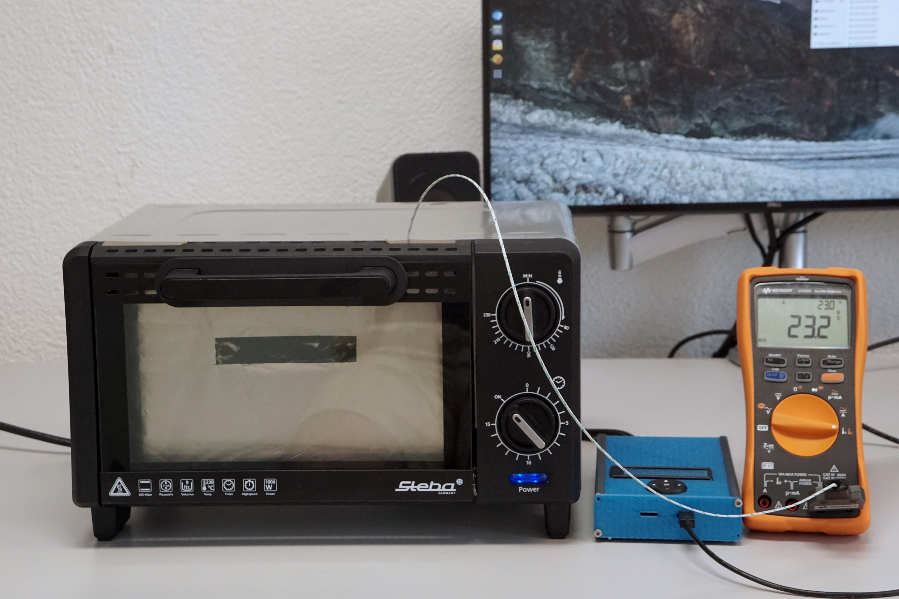
The first step is to analyse the performance and to try to make improvements. A small PCB with a thermocouple was placed in the middle of the toaster oven. Then the toaster oven was turned on to the max. A multimeter measured the temperature, which was logged on the computer.
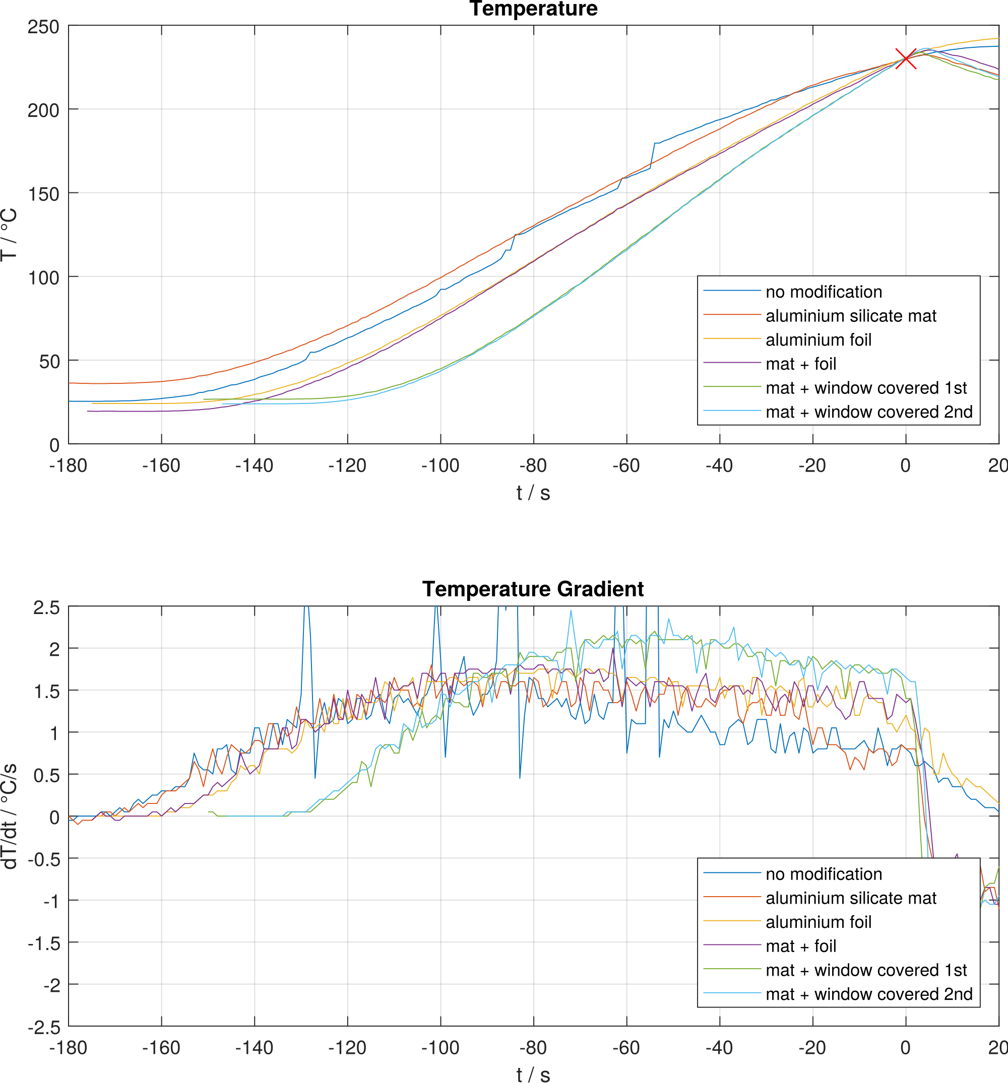
The image shows the temperature as well as the temperature change with different modifications:
-
Aluminium silicate mat: the toaster oven was covered in insulation mat. The plot (red) shows that this method did not improve the performance at all
-
Window covered half way: A lot of IR radiation can escape through the front window. To combat that the window was covered half way through with aluminium foil. This improved the the performance quite a lot (yellow, violet curve)
-
Window covered completely: The last change was to cover the front window completely (except a small cutout). This resulted in the best performance (turquoise, green curve)
The measurements show that temperature gradient can be greatly improved (from 1°C/s to of 2°C/s) by covering the window with aluminium foil. A inexpensive and easy measure.
It is important to be able to raise the temperature within a given time period to meet the solder profile requirements.
Control Theory
In this chapter we will examine the system model and design a controller. For this purpose Laplace transformation and the simulation software Simulink and Matlab will be used. However, this knowledge and software is helpful but not mandatory to design your oven toaster oven reflow controller.
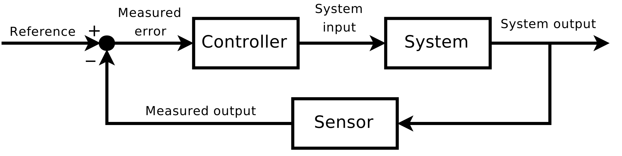
Source: Wikimedia Commons
The block diagram shows the basic structure of a control system.
System Model
A model is needed to simulate the system. The following transfer function is used:
The integrator (1/s) means that the power injected to the heat elements is accumulated as thermal energy.
The first step is to identify the measured curved. This is done by adjusting the model parameters until the measured temperature curve matches the model simulation.
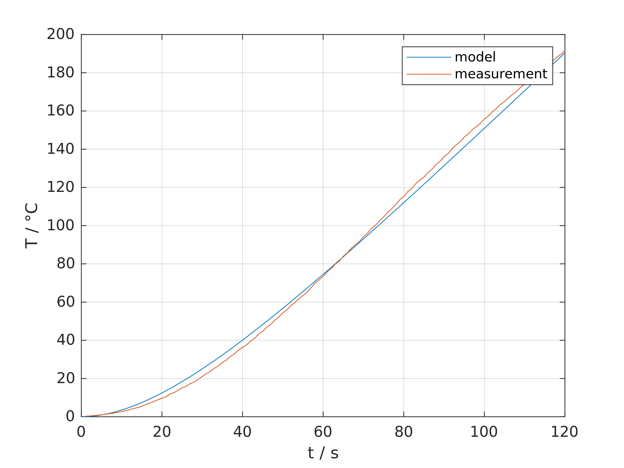
The plot implies that the temperature will always rise over time without any limit. This is flaw of our model, but this is not a real problem.
The resulting parameters are:
Controller
Next we need a controller to control the temperature in the toaster oven. PID controllers are easy to implement on a microcontroller and are well documented. The Integrator is not needed in this project because the system already has one. So a PD controller is used:
The following bode plot shows the open loop control path (blue) and the regulated system (red) in the frequency domain.
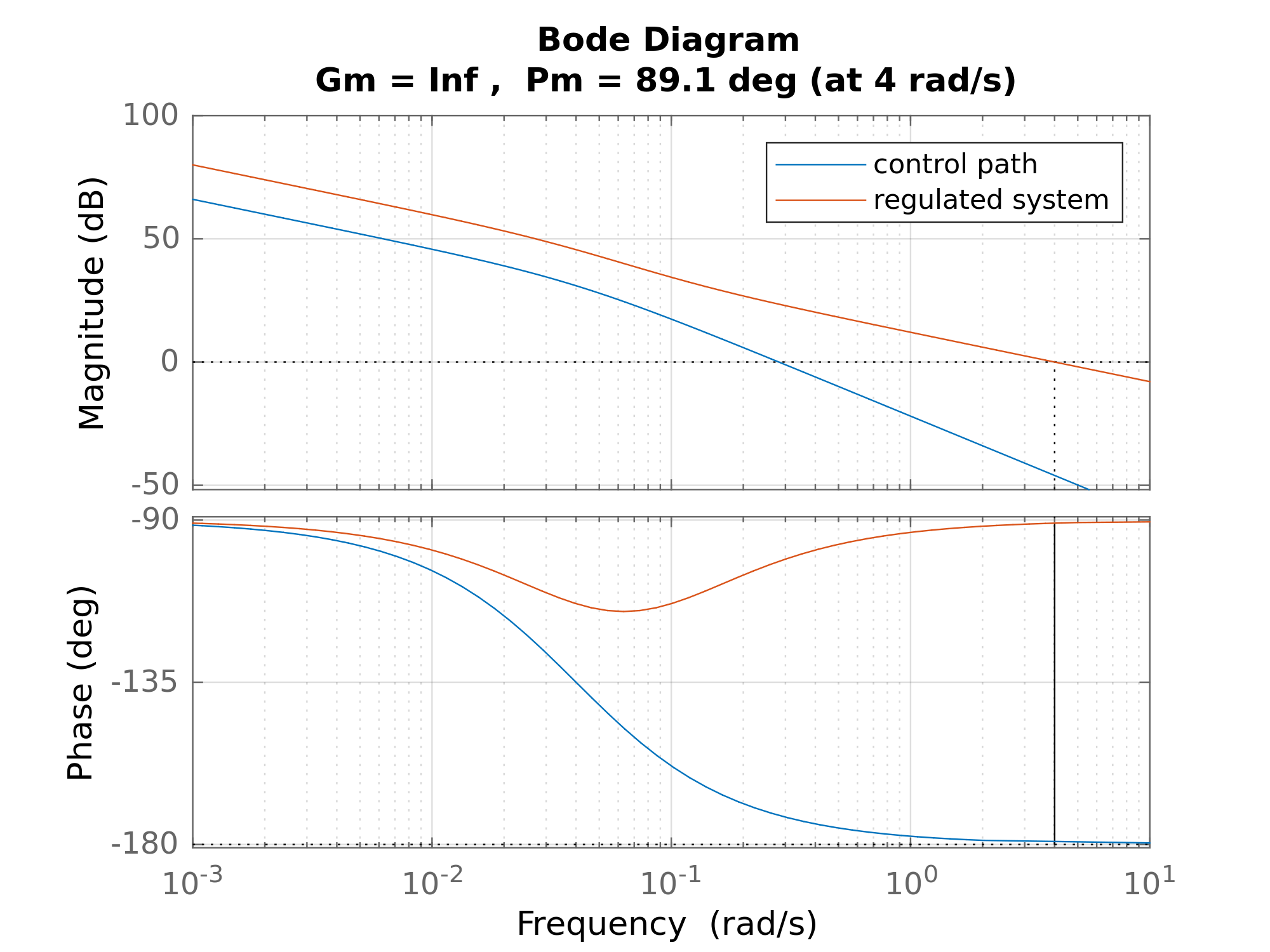
The goal here is to have a phase margin of more than 60° at the point the gain crosses the 0dB line and to increase the frequency at which the gain crosses 0dB. The aimed bandwidth is about 1 rad/s (it actually is 4 rad/s). To achieve that the derivative part (adds 90° to phase) of the controller is placed at 0.1 rad/s and the proportional part is set to 14dB. The simulated bandwidth is 4 rad/s and phase margin is 89°. These are both good values for this system. The resulting parameters are:
To implement the controller the transfer function has to be changed to the additive form:
Simulation
To test if the controller has chance to work in the real world, it has to be tested in the time domain.
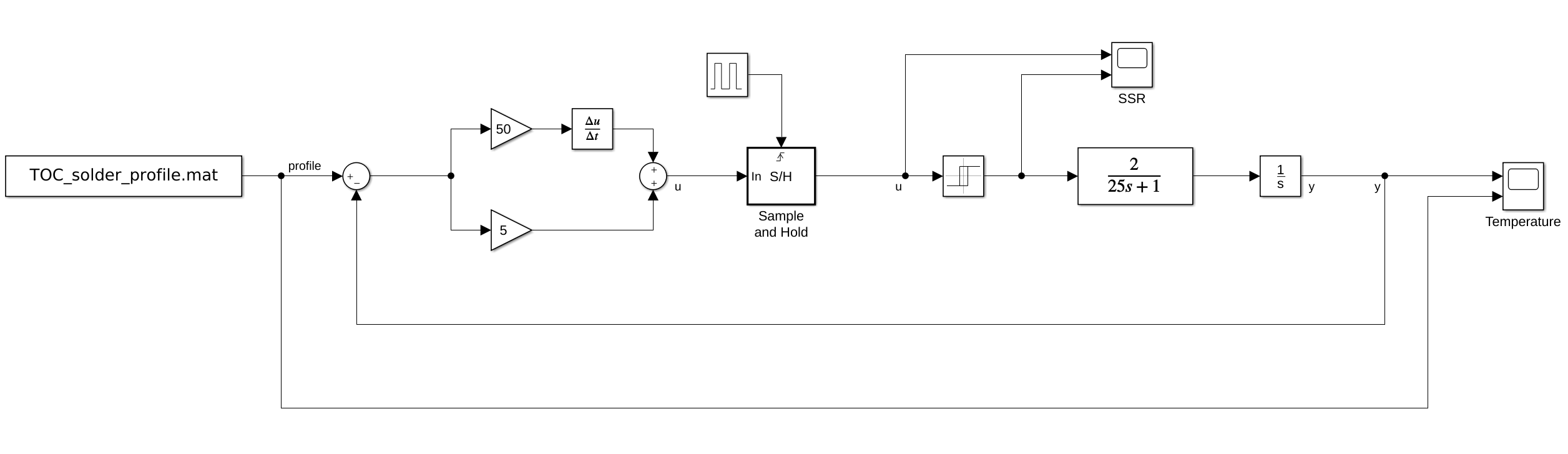
The schematics show the structure of the system. The simulation also takes into account that the heat elements are controller via solid state relay (SSR) and can only be switch on or off.
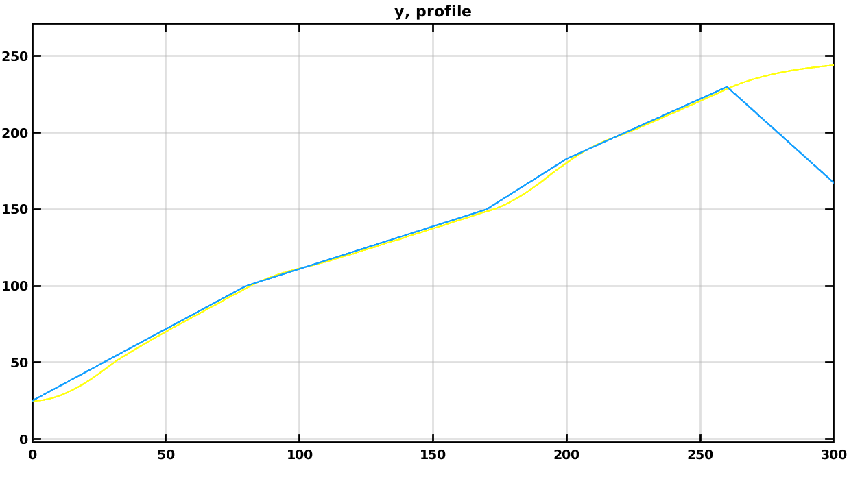
The temperature curve looks promising. The controller follows the the temperature profile (blue) within acceptable margins.
Instead of a system model and simulation based approach the controller parameters could also be evaluated manually.
Hardware
PCB Assembly
The following features are implemented on the PCB:
-
Power Supply 1: AC/DC converter from 110VAC-230VAC to 5VDC
-
Power Supply 2: Step down convert from 5V to 3.3V
-
Character Display (4 x 20 characters) to display the menu
-
Button Interface with arrows and ok button
-
Buzzer to alarm user
-
Thermocouple interface
-
2x 5V control outputs
-
Microcontroller (STM32F103R8), ARM Cortex-M3
-
Virtual COM Port over USB
-
SD card holder (no firmware implementation)
Electrical Setup
Some more components were needed to complete the project:
-
A Solid State Relay (Fotek SSR-40DA)
-
Some wires
-
A case for the electronics
Firmware
The basic project configuration was done with STM32CubeMX. This allowed to easily configure the hardware abstraction layer (HAL) and provided additional services like FreeRTOS.
CLion was use as IDE. This IDE requires a license but code can be compile with GCC.
The following features are implemented in the firmware:
-
Thermocouple reading
-
SSR control
-
PID controller
-
Simple menu system
-
Reflow profile selection
-
Current temperature display
-
-
FreeRTOS
-
Virtual COM port over USB (temperature logging)
The firmware project can be found on GitLab.
Test
The complete reflow oven was tested by soldering another project.

The plot shows the set temperature (blue) and the actual temperature (red). The temperature is not perfect and as good as the simulation but it is within acceptable margins.
The PCB assembly also looks fine.
The video below shows the reflow process:
Recommendations
-
Use a different character display, this one is obsolete and uses 5V logic
-
The buttons can replaced by cheaper ones
-
The PCB could also be mounted inside the toaster oven
Revision History
V1.0 Assembled and Tested, Some Errors
V1.1 Mistakes corrected in schematics and layout, no PCB was ordered
Design files
Authors
- /
- Active Participants


Components & Releases
Fabricate
Delete release
Are you sure you want to delete this Release?
This action cannot be undone.
Unable to download from CircuitMaker
You cannot download files inside CircuitMaker.
Please, open this page in browser and download file from there.
To copy hyperlink, press Ctrl+C with selected text below:


Comments ()