


Share by email
Your message was succesfully sent!
Add The Following Snippet To Your Html


DETAILED DESCRIPTION
Functionnality
This design convert a PWM signal with two pulse width value possible into a two-state logic signal.
Typical use is for RC receiver, when a two-state channel has to drive a logic circuit.
Advantages:
- Fast response : the output is refreshed at each period of the PWM signal.
- Noise immunity: analog signal part is minimized.
Principle:
- At each period, the PWM signal charges the RC cell.
- Depending of the lenght of the pulse, the RC cell's voltage reachs the comparator's threshold or not.
- The end of the PWM pulse produces a falling edge.
- The D flip-flop captures and hold the comparator's output value until the next period.
RC cell dimensioning:
The time constant of the input RC cell must be chosen to maximise the voltage difference betwen a charge with a long pulse and a short pulse. Therefore, the time constant should be solution of this equation:
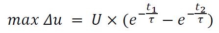
with :
- U : high voltage of the PWM signal.
- t1 : short pulse lenght.
- t2 : long pulse lenght.
Example values:
- U =3V
- t1 = 1ms ⇒ tau = 1.4 ms and du = 0.75 V
- t2 = 2ms
Threshold comparator value:
The threshold value must be between the two charge peak voltage, and closer of the highest peak for better noise immunity.
Design files
Authors
- /
- Active Participants


Components & Releases
Fabricate
Delete release
Are you sure you want to delete this Release?
This action cannot be undone.
Unable to download from CircuitMaker
You cannot download files inside CircuitMaker.
Please, open this page in browser and download file from there.
To copy hyperlink, press Ctrl+C with selected text below:


Comments ()