


Share by email
Your message was succesfully sent!
Add The Following Snippet To Your Html


DETAILED DESCRIPTION
Introduction
Infinity Drive is a drive pedal used for guitars and basses that enables access to a very wide variety of tones at your fingertips. If you think of any standard overdrive pedal (think Boss OD1 or SD1) your usual controls would be volume, gain and tone (Boss OD1 doesnt have a tone control) you are limited to its tonal capabilities by the fixed clipping circuit, tone control circuit and amplification circuits. The heart of an overdrive pedal is the clipping circuit. Two diodes in opposite directions are placed between the output of an op amp and the inverting input of the same op amp. Once the output signal of the op amp exceeds the threshold voltage of the diodes the excess signal is fed to the inverting input, thus reducing the amplification factor (gain) of the op amp. Therefore the peaks and the troughs of the signal are actually rounded off. So thats how and overdrive pedal works. Infinity drive offers many different combinations of clipping circuits and tone control options to add diversity to your sound.
How is infinity drive different and how does it work?
Infinity drive consist of two sections in one pedal, namely Boost module and the Drive module.
Drive Module
Lets talk about the Drive module first. The drive module consist of four sections.
- Input equalizer
- Clipping section
- Output Equalizer
- High cut control
1. Input equalizer.
The Input equalizer acts as an equalizer that changes the tonal character of the output signal of the guitar before it becomes overdriven. The input equalizer helps you to effectively tighten up the bottom end of the guitar for a good rythm tone, or brighten the top end of the spectrum for a shimmering clear lead tone. Let me give you an example. If you do know a bit of music and follow several bands you may understand this a bit clearer, but I will explain what goes on. if we increase the bass end of the signal before it is overdriven, you can get a tight, booming low end rythm tone. The sound will never sound muddy like the ouput equalizer which is later to be explained, but the bass end will tighten the guitar up and give a good, dark rythm tone ( think AC/DCs Malcolm Young. Listen to Rock or Bust by AC/DC). Malcolm Young doesn't use a pedal to tighten up the bass end, but his choice of amplifiers are designed to naturally tighten up the bass and give a dark tonal character. Then say that we add a lot of middle frequencies to the input signal, we would get a fat sounding, saturated tone which is good for anything between blues and rock (think BB King, and Ritchie Blackmore). Having lots of midrange is a key element of retaining clarity under high gain settings and keep the tone lively and rich. To really sparkle up your tone you can add the treble (think Angus Young of AC/DC). Angus uses plenty of top and to achieve that fiery lead tone and have plenty of presence. And again it is Angus' choice of Amplifiers that give him that sparkly high end. However having too much treble can lead to instabitility of tone and cause a sonically unpleasant feedback compated to the feedback from lots of mids. The input equalizer offers 20dB of cut or boost of bass, middle and treble frequencies at wide bandwidths.
2. Clipping section
The clipping section is the heart of any drive pedal. The clipping section takes the excess signal from the ouput of the op amp used for driving the signal and feeds it into either the inverting input, non inverting input, or the ground. If we take the output of the op amp and feed it into the inverting input via two diodes wired in parallel (one for +ve voltage and the other for -ve voltage) we effectively feed the signal above the threshold voltage (excess signal) of the diode reducing the amplification factor (gain) of the op amp. This means that when the excess signal above the threshold is fed into the inverting input, the peaks and the troughs of the signal become more rounded off and flattened. the image below shows how a sine wave is rounded of by overdriving.

Source signal is the original signal without being overdriven. Clip level is the threshold voltage of the diode (where the clipping starts) and the knee level is the new amplitude after being overdriven. the closer the knee level and the clip level are, the harsher the overdriven sound. Assymetry occurs mainly in tube ampifiers being overdriven. When a vacuum tube/valve undergoes overdrive it clips differently on either side and that resembles the clipping shown on the diagram. There are many forms and shapes of asymetric clipping but we will talk about that in a while. Asymetric clipping sounds more pleasing to the concerning ear. What if we take the excess signal and feed it into the non inverting input of the op amp we increase the amplification factor of the op amp. The op amp will amplify further and it will point the peaks and troughs of the sine wave. The below diagram will explain this.

The distorted sine wave shows a more raised peak character compared to the nromal wave because the distortion has started after the signal has begun to level off. Distortion gives the sound a more harsher, saturated, sustained tone with lesser warmth than overdrive. What if we ground the excess signal from the output of the op amp? Then we get fuzz. Fuzz is used by modern rock artists and usually clips the sine wave so much that it forms a square wave as shown below.
As we see in this diagram the signal is harshly clipped into a square wave.
In the clipping section the user can use a wide array of clipping diodes in order to change the characteristics of the overdriven sound to taste. The clipping options are split into the +ve and -ve signal sides. For each side an array of 8 clipping components (diodes and FETs) are present. They are 1N34A germanium diode, BS170 MOSFET, BAT41 schottkey diode, BAT46 schottkey diode, 1N4148 silicon diode, UF4007 silicon rectifer diode, 4728 zener diode and an IR LED (listed here in increasing order of clipping harshness). Each side of the signal has its own array of the above set of diodes, forming a total of 16 diodes. You can mix and match any type of diodes as you like. Even running more than one diode on each side is possible, increasing the headroom until overdriven. Asymetric clipping is achieved by using two different typed of diodes on either side. But anyways you can set how much you want to drive the diodes by the drive gain knob. Below are a few exemplar waveforms of some of the clipping diodes in overdrive mode.
Clean wave with no active diodes
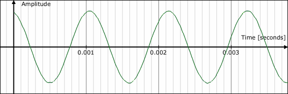
Germanium diodes
Noticably slightly clipped than the clean signal
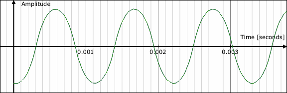
Schottkey diodes
Even more compressed than the germanium diodes
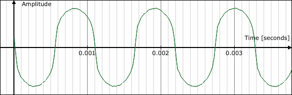
Silicon diodes
Harder clipping at a higher headroom
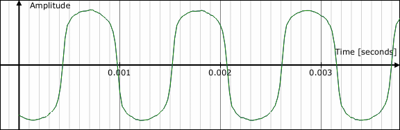
Rectifier Diodes
Very similar waveform to the silicon diodes clip
So those are some examples of the different clipping diodes waveforms. I took those diagrams off this site; http://diy-fever.com/effects/the-ultimate-overdrive/. Bane, the owner of the site has built many DIY stomp boxes and has been the main idea behind infinity drive. So here's a shoutout to Bane for the idea of the possible clipping properties and the oscilloscope observations of clipping. However he had an issue with the op amp clipping before the clipping threshold of some other diodes (OPA4134PA op amps having a headroom at 0.7v) therefore I used the TL072 op amps for more headroom (2.5v). However if you really do want some square wave op amp clipping you can run the boost module in front gunned up till maximum and the drive volume set as you like, which will be later explained. The pre gain knob controls how hard the clipping section is pushed. pre gain is diffrent to gain since where gain controls the proportion of clipped signal to bypasses signal of of the feedback loop into the inverting input of the op amp. The pre gain sets the gain of the input buffer so it amplifies the initial level of signal pushed into the drive module, wheras the gain knob controls how much clipping you get from the diodes. The pre gain is included to boost up weaker single coils and vintage pickups. The other purpose is so that you can decide the sensitivity of the gain knob by setting where the pre gain knob is. So if you want to quickly set another drive setting during play, having the pre gain set low reduces the sensitivity of the gain knob to change in drive harshness, where as when pre gain is set high for every tiny change in position of the gain knob you get a very different harshness of clipping. After you have tweaked the clipping section you can set the final drive volume by the drive volume knob. Thereby we move to the end of the clipping section.
3. Output Equalizer
The output equalizer is pretty much the same as the traditional equalizer control as a standard amplifier with three bands. The output amplifier controls the proportions of the overdriven signal into bass, middle and treble. This is very standard on many amplifiers and some pedals (think Seymour Duncan 805). The output equalizer offers 20dB of cut or boost of bass, middle and treble frequencies at wide bandwidths. Always keep it a top tip to have lots of mids because usually in a band situation the guitars often for the middle and top frequencies. so having exta mids is quite pleasant. To prevent the mids becoming muddy the mid control is voiced at 1kHz, compared to the 400Hz of a Fender or 700Hz of a Marshall or Vox amplifier. But its a wide band equalizer so you need not worry of any unpleasantly focusses bump in the frequency spectrum on adjusting any of the equalizers. However if you are playing funk or metal or any 'underground genre' go ahead and kill the mids if you like it ;)
4. High cut control
The high cut control allows you to set a cutoff frequency to the driven signal. It can be adjusted between 20kHz and down to 1kHz. I usually would set it to 10kHz to stop white noise at high gain levels (think EVH 5150 vs a Marshall JCM800). At low gain levels you can leave it open as high as you like to make the tone sparkle brightly but as you crank up the gain to hard rock levels gradually turn down the high cut in order to prevent your guitar from fizzing out.
That is the end of the drive module.
Boost module
The smaller, simper section of this pedal is the boost module. The boost module has 2 sections.
- High cut control
- Volume control
1. High cut control
The high cut control is also the exact same circuitry as in the drive module. When in parallel chain mode you can set the high cut frequency very low to allow only the bass through so you can get some pretty deep subsonic tones without the loss of low end which is a common problem on high gain drive settings. The high cut control on the boost module now goes down to 40Hz, which is much lower than that of the drive module. On series chain mode running into or out of the drive module you can set the boost module as a high cut filter engager which can effectively alow you to interchange between dark rythm tones and bright lead tones or vice versa as you like.
2. Volume control
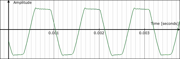
The volume control simply controls the overall output of the boost module. Volume control can be used to get some fuzzy hard clip from the op amps themselves like shown below, increase volume of the drive module, or increase the driven harshness of the drive module.
Thats the end of how the whole pedal works.
How to make the pedal
The most important thing to undertsnd when making circuits using circuitmaker is how circuitmaker works and how does it help you build what you want and how to get the most out of it. I found this article on the internet and I decided to share it with everyone. So here it is. https://documentation.circuitmaker.com/display/CMAK/From+Idea+to+Manufacture+-+Driving+a+PCB+Design+through+CircuitMaker. Circuitmaker is a powerful editing and creating tool for making electronic circuits for a variety of people from the hobbyst to the professionals. A great trick I found is that understanding whaat a PCB in circuitmaker means. It shows you the locations and routes for components. To start off with we must understamd what a footprint is. A footprint is a drawing that shows the exact locations and actual size and look in real life so it can be implemented on a PCB. A footprint determines the shape and the size of a component. For example say that you cannot find a 510K ohm resistor in the octopart library. No worries. Go for a 500K ohm resistor and it will solve the problem as long as the physical appearance of the objects are the same. You may find many of such situations in designing a schematic and PCB in circuitmaker, but I've done that part for you guys. Keep it a top tip that you need not have the exact same components to make your circuit succesful on cicuitmaker, you just need to have components with the same physical appearance on the PCB. However when you are actually assembling the components in real life on your PCB always go for the exact components, or very close if you do not manage to obtain them. When designing a PCB make it a point to know that you can route under individual components as well. You need not restrict yourself to routing around components, you can route underneath components. The major advantage of routing underneath components is the lower distance or routing (which means lesser noise with lots of gain in the case of infinity drive) and the ability to avoid jumpers as much as possible. Keeping these two techinques in mind I was able to wire all the components quite neatly and needing only three or four jumpers in total for the whole device. If you do want to make things even more simpler and straighforward in terms of routing however you may need to be extremely careful in terms of producing the PCB routed as mistakes are easily introduced preventing the perfect alignong of the top and bottom layers. Therefore I decided to go for a single sided PCB. But you can always opt to produce a double sided PCB as well.
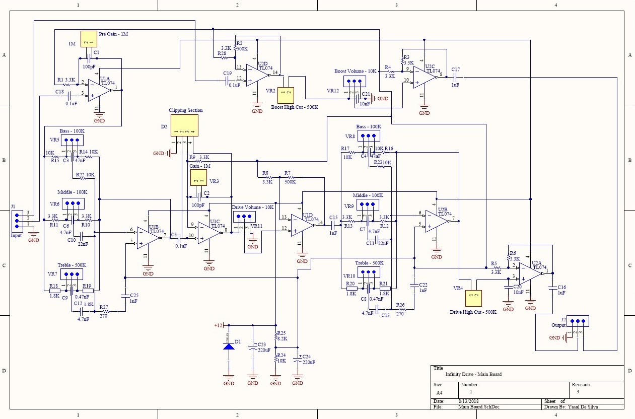
Below is an image of the Schematic in the schematic editor mode.
Below is an image of the PCB with the routing in the 2D PCB editor mode.

Below is an image of the PCB in 3D in the PCB editor mode.

List of Components
Number of components needed are alongside the component in brackets. All components must be through hole mounted.
- Copper board
- Project box 15cm*10cm (1)
- 1/4 Inch mono audio jacks (8)
- DC power jack (1)
- Knobs for pots (12)
- 3 pin on-on toggle switches (20)
- 9 pin on-on footswitch (2)
- 14 pin IC bases (2)
- tl074 quad op-amp ICs (2)
- 3.3K ohm 0.25W resistors (12)
- 10K ohm 0.25W resistors (7)
- 1.8K ohm 0.25W resistors (4)
- 500K ohm 0.25W resistors (3)
- 270 ohm 0.25W resistors (2)
- 8.2K ohm resistor (1)
- 0.1uF ceramic capacitors (3)
- 1uF ceramic capacitors (3)
- 47nF ceramic capacitors (2)
- 4.7nF ceramic capacitors (4)
- 0.47nF ceramic capacitors (2)
- 1nF ceramic capacitors (2)
- 22nF ceramic capacitors (2)
- 100pF ceramic capacitors (2)
- 10nF ceramic capacitors (2)
- 220uF 25V electrolytic capacitors (2)
- 500K logarithmic potentiometers (4)
- 1M logarithmic potentiometers (2)
- 10K logarithmic potentiometers (2)
- 100K logarithmic potentiometers (4)
- 1N4148 Diodes (3)
- 1N34A Diodes (2)
- BS170 MOSFET (2)
- BAT41 Diodes (2)
- BAT46 Diodes (2)
- UF4007 Diodes (2)
- IR LEDs (2)
- Red LEDs (2)
- Solderless Wires - Male to Male (40)
- Connectors for solderless wires - Female (80)
- Copper dot board (1)
- FeCl3
- Water
Design files
Authors
- /
- Active Participants


Components & Releases
Fabricate
Delete release
Are you sure you want to delete this Release?
This action cannot be undone.
Unable to download from CircuitMaker
You cannot download files inside CircuitMaker.
Please, open this page in browser and download file from there.
To copy hyperlink, press Ctrl+C with selected text below:


Comments ()